Everybody like realistic water in their games, but it can be a pain to implement if you aren’t familiar with shader programming. Thankfully, Unity has a fantastic tool called Shader Graph that allows you to create shaders visually. This tutorial is aimed at beginners who have a basic understanding of how to use Shader Graph. I felt that most of the existing resources for wave simulation are needlessly and prohibitively complicated. This tutorial will briefly cover the mathematics behind Gerstner Waves as well as provide a step-by-step guide on how to implement wave simulation into a Shader Graph.
Mathematics of a Gerstner Wave
Before we jump into actually creating the shader, let’s take a look at the math behind a Gerstner Wave.


The image above is a lot to take in, but thankfully you don’t actually need to know all of it to simulate a realistic-looking wave. Here’s a brief overview of what you actually need to know:
- ξ and η are the x and z components respectively. The math behind them is virtually identical, barring a single substitution.
- ζ is the Y component. It’s made up of the amplitude and the cosine of θ
- α and β are the x and z values of an affected vertex.
- w^2 is the wavelength. The frequency of the wave can be derived from the wavelength.
- h is the wave depth/height
- θ is theta. In this scenario, it represents the sum of the wave direction and vertex position, minus frequency multiplied by period/time.
- f is the frequency of the wave
- w is the wavelength
- pos is the position of the wave as a 3D vector.
- dir is the direction of the wave as a 3D vector.
- t is
- v is the speed of the wave.
- m is the magnitude of the wave.
- d is the depth of the wave.
- a is the amplitude of the wave.
- f = √tanh(m * d)
- θ = ((dir.x * pos.x) + (dir.z * pos.z) – (f *t)
- y = cosθ * a
- v = f * w
- w = v/f
That’s it. That’s literally all you need to know as far the mathematics goes.
Time to make the actual shader.
Creating the Shader Graph
Open up Unity and create a new project using the Universal Rendering Pipeline (URP). The most recent versions of Unity include Shader Graph in the URP. If you are using an old version of unity, you may have to install Shader Graph using the Package Manager. You can find this under the Window dropdown at the top of the screen.
Frequency Sub-Graph
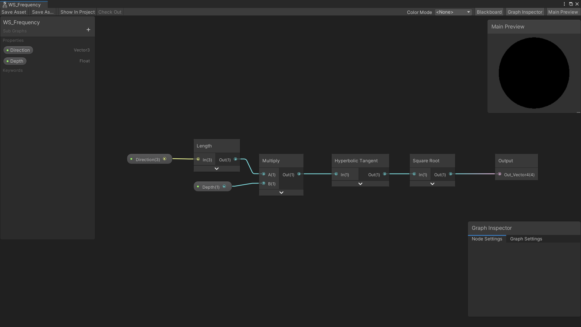
To get the frequency of the wave, you need to work backward from your output node. Create a Vector3 and Float property for Direction and Depth respectively. This subgraph is getting a representation of f = √tanh(m * d). Frequency is a decimal value, so make sure you select the output node and change it from Vector4 to a float. That’s all there is to this sub-graph.
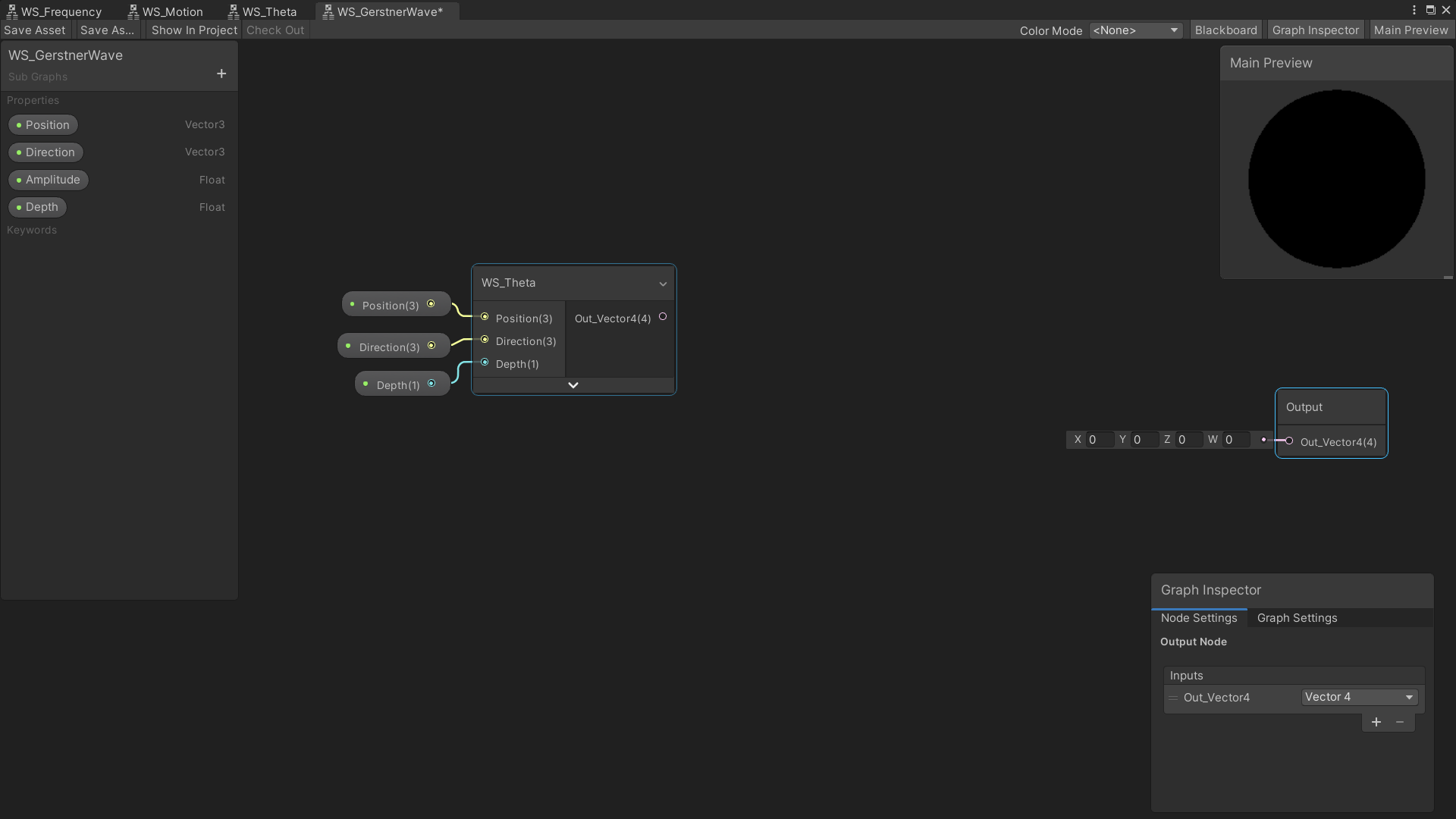
Theta Sub-Graph
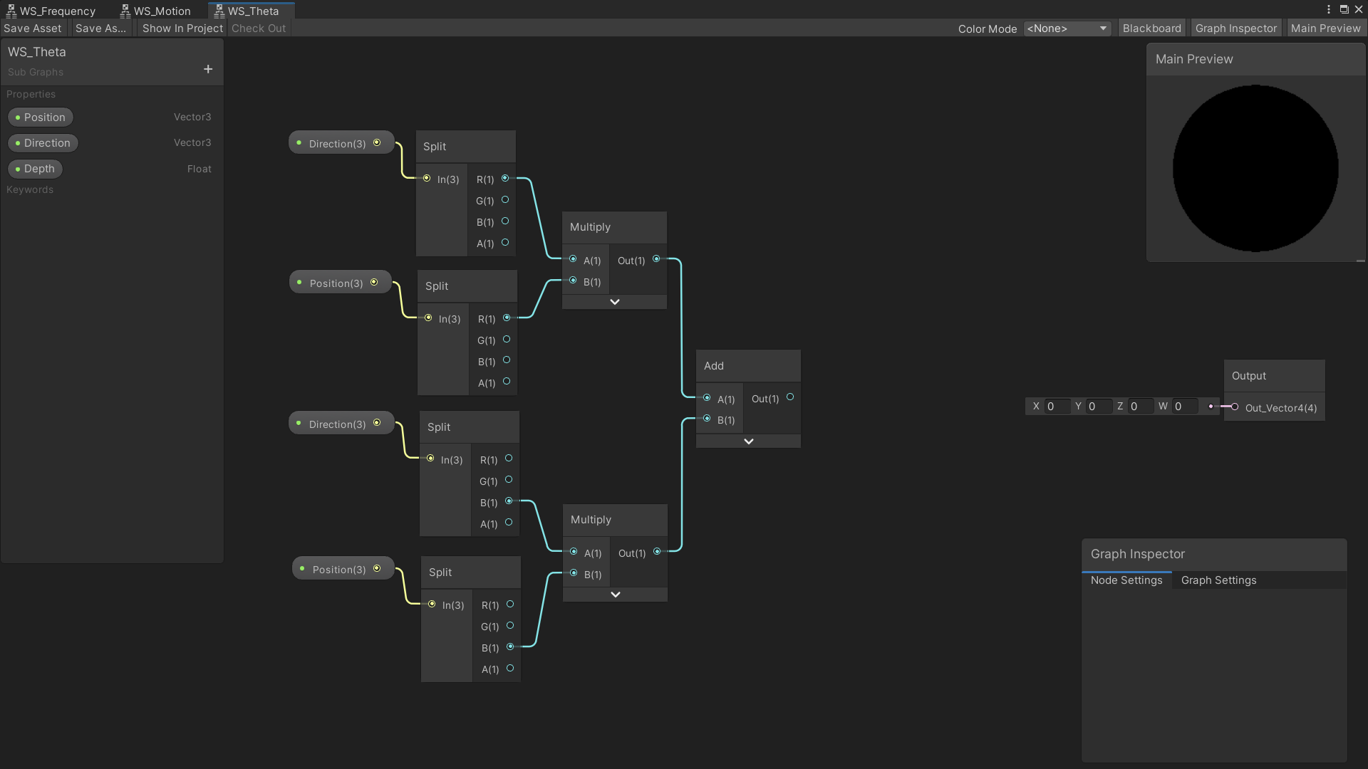
Theta is equal to ((dir.x * pos.x) + (dir.z * pos.z) – (f *t). Let’s start off by splitting, multiplying, and adding the x and z values of direction and position. Create Vector3 properties for Position and Direction, as well as a Float for Depth. The split node is typically used for breaking apart the color values of Red, Green, Blue, and Alpha, which is represented as a Vector4. As a result, the values for R and B also correspond to the X and Z values of a Vector3 or Vector4. Split and multiply together the positions and directions of x and z, as shown in the image above.
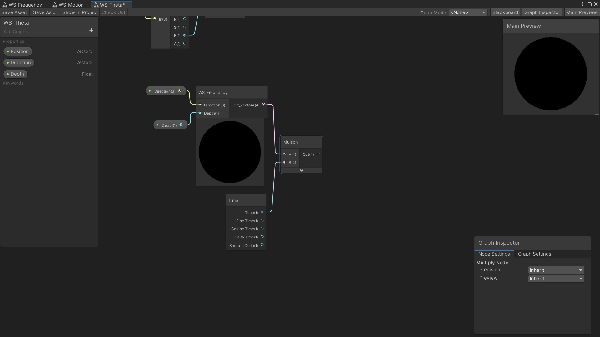
Now let’s get the frequency part of the theta calculation. Create a node of the Frequency Sub-Graph, plug in the direction and depth variables, and then multiply the frequency by time.
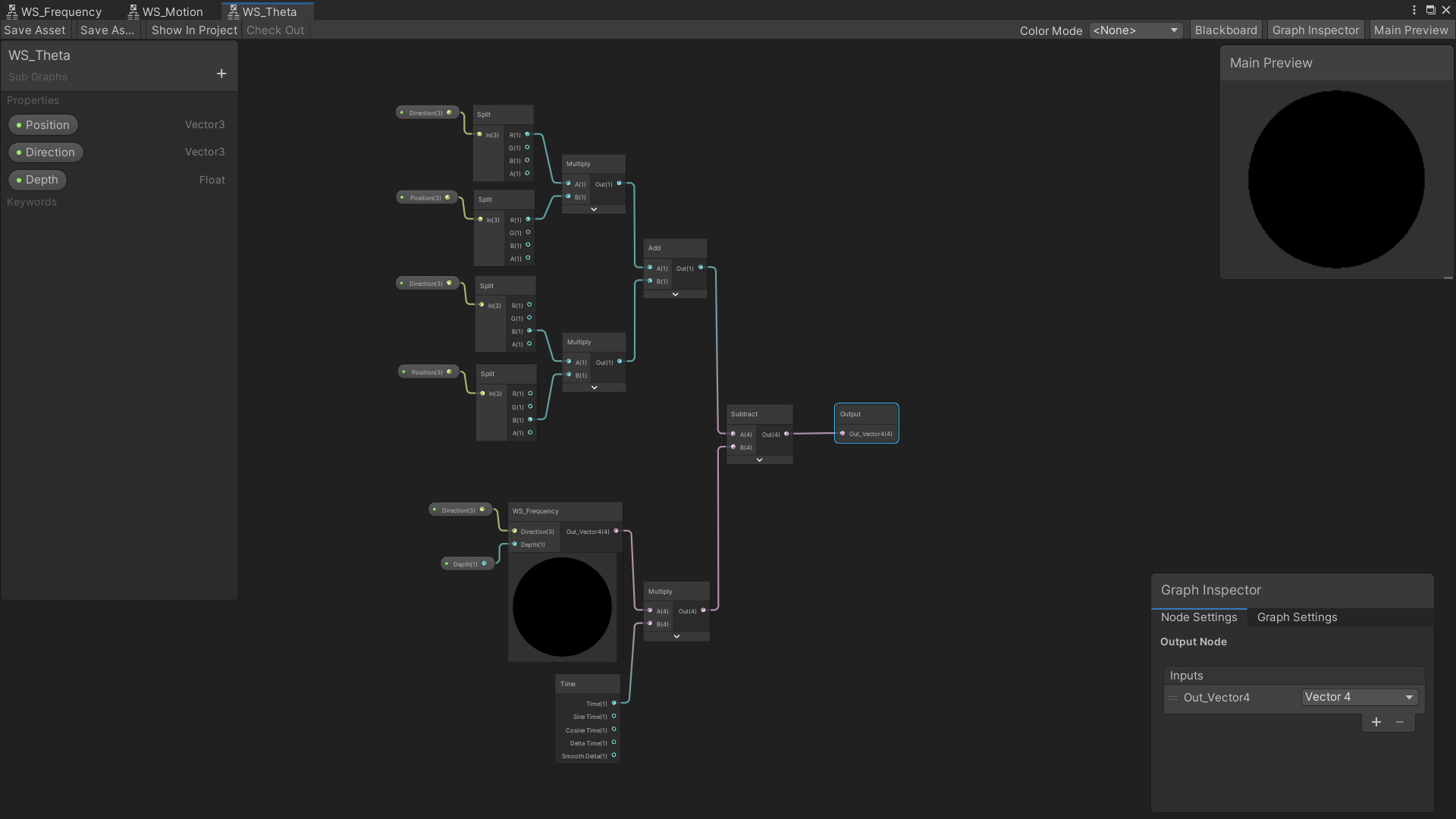
Then you need to subtract the frequency * time value from the result of (dir.x * pos.x) + (dir.z * pos.z) calcuation. Plug the final subtract node into your output. Make sure you select the output node and change it from a Vector4 to a Float.
Gerstner Wave Sub-Graph
Start by creating Vector3 properties for Position and Direction, and Float properties for Amplitude and Depth. Create a node for the Theta Sub-Graph and plug in the approriate properties.
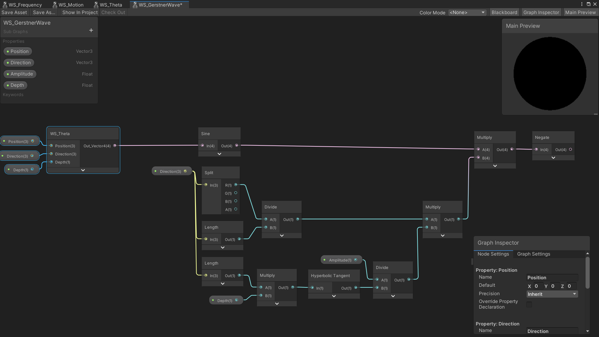
Follow the image above. This is the ξ component of the expressions shown at the very beginning of this tutorial. The sine of Theta is being multiplied by (x of direction / length of direction) * (amplitude / tanh(length of direction * depth)). You then flip the sign of the resulting value.
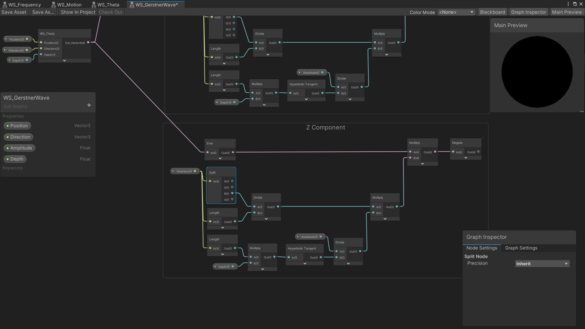
For the Z component, copy the previous nodes, and change the output of the split node from A to B.
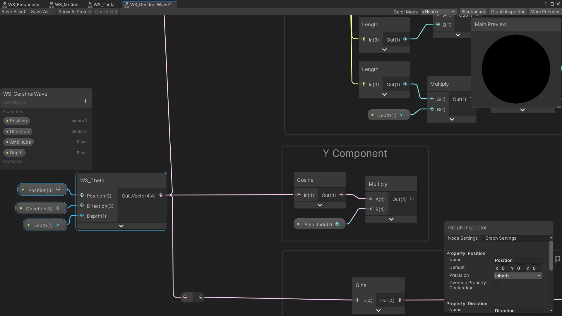
For the Y component, you just need the Cosine of Theta multiplied the Amplitude of the wave.
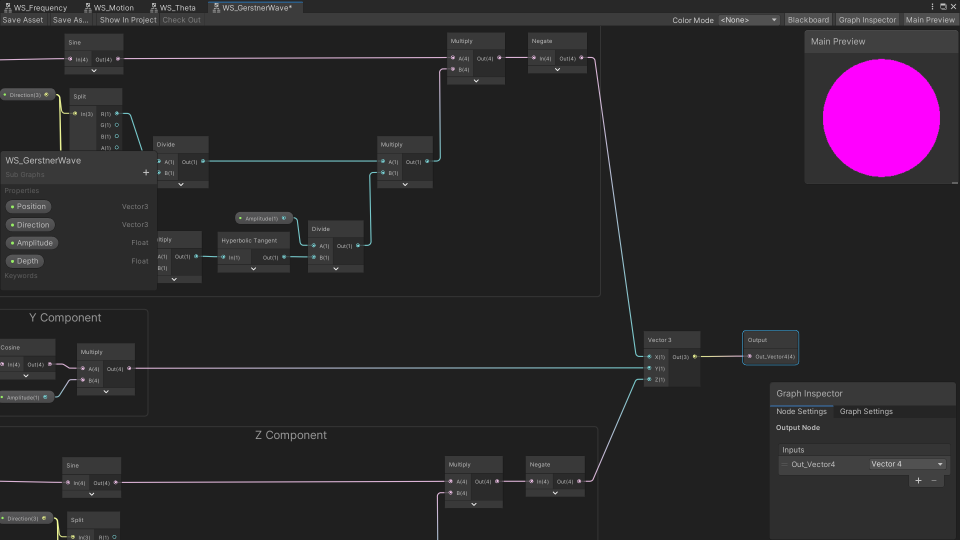
Plug the results of the x, y, and z components into a Vector3, and then connect that vector to the output node. You should change the output node to a Vector3, although leaving it as a Vector4 won’t have any real consequences.
Wave Shader Graph
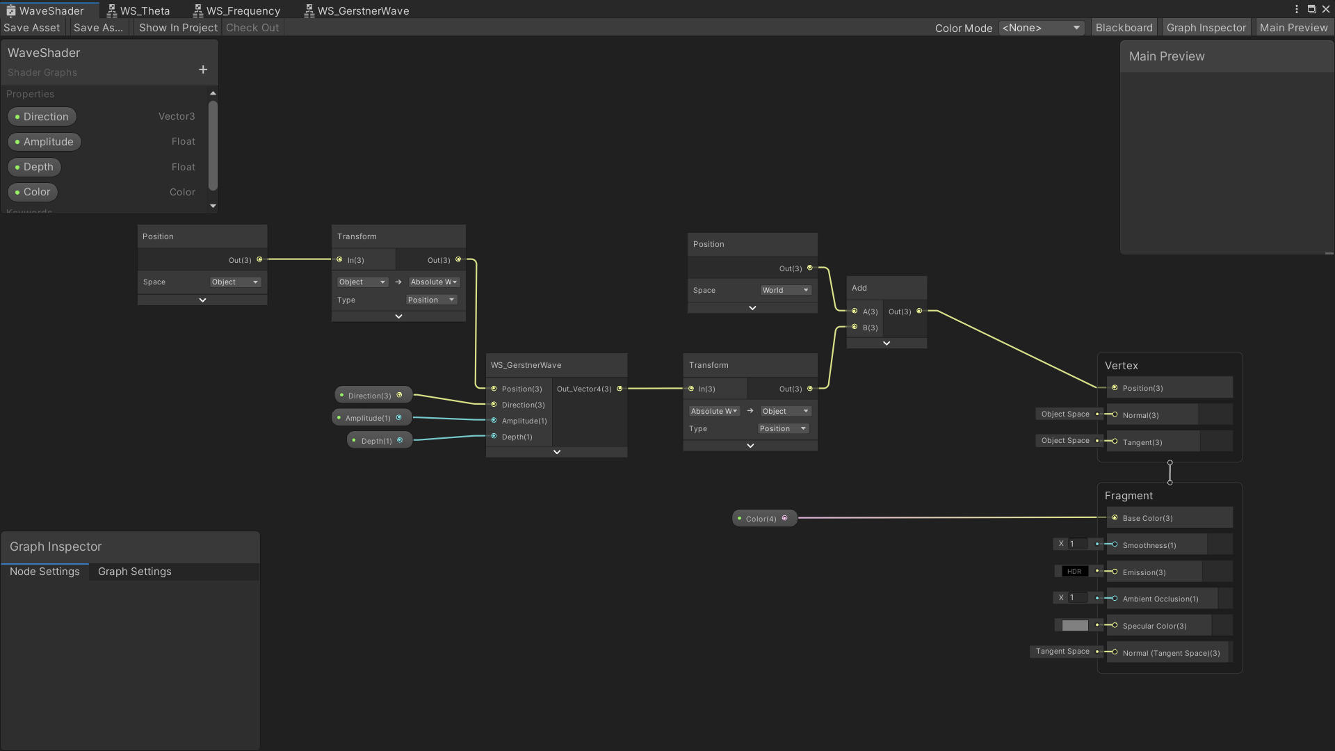
Open up your Lit Shader Graph. Create properties a Vector3 property for Direction, Float properties for Depth and Amplitude, and optionally, a Color property.
Create a node for the Gerstner Wave Sub-Graph and connect the Direction, Amplitude, and Depth properties.
Then create a position node set to object space, and then transform it from object to absolute world space. This value is then to be used as the position value for the Gerstner Wave Sub Graph. The output of the Gerstner Wave then needs to be transformed back into object space. Add the world space to the resultant and then connect the add node to the Position on your master node.
Go back into the unity editor and create a material using your completed Shader Graph. You should end up with a material that looks something like this. I used a direction of (0.5, 0, 0.5,), an amplitude of 0.3, and a depth of 1.
How to (Poorly) Recalculate the Normals
There’s just one thing missing. The lighting on our shader is all wrong. You can only see the waves on the edges of the mesh. To fix this, we’ll need to recalculate the normals of our mesh. Unfortunatly, recalculating the normals needs a whole tutorial by itself. I highly reccomend the tutorial created by Game Dev Bill. His tutorial goes very in-depth on how to properly calculate normals for your shader.
That being said, I’ll give you an example of an incredibly rough normal calculation so that you can at least see what your wave shader looks like. I strongly reccomend that you don’t use this method for anything other than learning or experimentation.
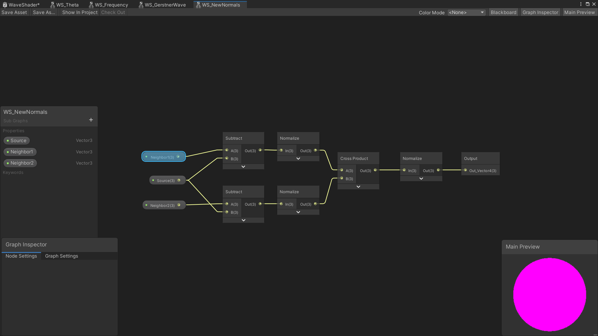
Create a new subgraph, and create Vector3 properties called Source, Neighbor 1, and Neighbor 2. Then, just follow the image above. Make sure your output node is set to Vector3. I won’t go into depth about how this works, because by all accounts it’s not a great way of doing things.
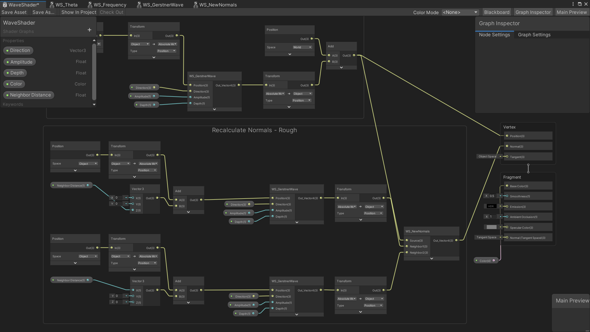
Go back to your main Shader Graph and create a float property called Neighbor distance. You want to plug those into the x and z values of two Vector3 nodes, and then get the sum of those values added to the absolute world position. Create 2 Gerstner Wave nodes and use the sums of the x and z neighbor distance calculations to each Gerstner Wave. Plug the rest of the appropriate properties into the Gerstner Wave nodes, and then transform them back into object space. connect the results to a New Normal node. Also, you’ll want to add the result of the vertex position into the Source input. You should end up with something that looks like this:
As you can easily see, the result is less than ideal, but it gives you a good indication of how your waves look. In the next tutorial, I’ll cover how to add multiple Gerstner Waves together to form more realistic looking waves, as well as how to implement various visual effects to your shader.